Mold Terminology
Before exploring molds further, it is first helpful to understand some terminology that is commonly used to describe molds and mold features. Molds can also be referred to as tooling, patterns, masters, plugs, blanks, or bucks. There are some slight differences between these terms though.
A “mold” or “tool” is used to form a composite part. A mold pattern or simply a pattern, master, plug, blank, or buck is the structure used to create a mold. Molds are often created by first shaping a pattern which is a geometric negative of the mold. Mold patterns are essentially a simple mold used to create a more advanced mold.
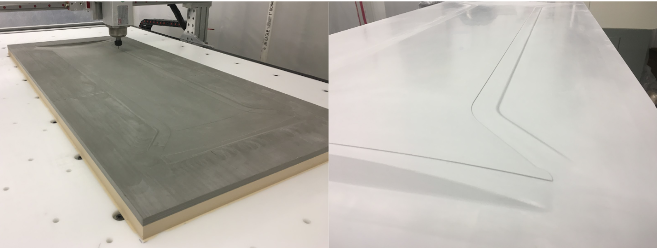
Left Image: Female center spar mold pattern used for the DarkAero 1 aircraft. The pattern was CNC cut from polyurethane tooling board which is easily machinable but is not suitable for use as a production mold material.
Right Image: Male center spar mold for the DarkAero 1 created from the mold pattern. The mold was made from epoxy gel coat supported by a carbon fiber backing structure. These materials are dimensionally stable and robust enough to use for production molds.
The general shape of a mold can be categorized as either male, female, or closed. Male molds have positive geometry such as a convex dome shape, and the fiber reinforcement is placed on top of the mold surface. Female molds, also known as cavity molds, have negative geometry such as a concave bowl shape, and the fiber reinforcement is placed down into the mold. Both male and female molds are used for wet layup, wet layup + vacuum bag, infusion, and prepreg manufacturing processes. Closed molds, also referred to as clamshell or compression molds, include both a male and female half that fit together with matched geometry. The fiber reinforcement can be positioned on either the male side or female side or both mold faces. Closed molds are often used with the resin transfer molding (RTM) or bladder molding manufacturing processes.

Left Image: Example cross section of a simple male mold.
Middle Image: Example cross section of a simple female mold.
Right Image: Example cross section of a simple closed mold.
An important geometric property of a mold is its draft angles. A mold can contain zero draft, positive draft, or negative draft angles. Draft angles play a critical role in removing a cured part from its mold. Depending on the layup schedule and stiffness of a part, negative draft angles can make part removal challenging or impossible without damaging the part and/or the mold. A zero draft angle can also make part demolding challenging depending on the size of parallel vertical mold faces and the stiffness of the part. The deeper the walls of a mold, the more sliding friction that must be overcome to remove a part from the mold. Positive draft angles provide the best opportunity for part demolding and should be incorporated into the mold design if possible. If deep walls with zero draft or negative draft are unavoidable, a multi-section mold may be necessary or the part may need to be broken up into multiple segments to allow for demolding.

Left Image: zero draft. Middle Image: positive draft. Right Image: negative draft.
Multi-section molds contain two or more segments that can be fastened together to form a larger mold or a mold with complex geometry that would otherwise make demolding challenging if it were built in a single piece. Multi-section molds can also be classified according to whether they have male, female, or closed geometry.

Example of a multi-section female mold containing left and right halves.
Mating segments of multi-section molds must include alignment features or locating features. These features precisely position and constrain each mold section relative to the next in all directions. Examples of locating features include mating flat faces between mold sections as well as using bolts or locating pins to align sections together.

Red arrows indicate bolt hole alignment features added to an aluminum closed mold used to manufacture composite tube connectors for the DarkAero 1.
In addition to the design details listed, molds can have a number of other important features. Examples of these features are illustrated in the following images of the vertical stabilizer mold for the DarkAero 1. This mold was designed to form a carbon fiber laminate through an infusion process and therefore requires a near perfect vacuum seal. Numbers 1 through 4 call out important mold features.

Features on the mold for the left vertical stabilizer skin of the DarkAero 1.
1) Tool Surface: The main surface area of the mold establishes the basic geometry of the vertical stabilizer and rudder skins. This region is referred to as being “on the part”. The perimeter flange outside the part boundaries sits “off the part”. The surface finish of the mold will determine the surface finish of the part, the longevity of the mold, and the ease of part removal. This mold was sanded to a 400 grit surface finish.
2) Part Edge Feature: These small (0.03” high) step features define the outer perimeter of the part and directly form an accurate trim feature around the boundaries of the part.
3) Mold Flange: The mold is built larger than the actual part geometry. The extended area around the perimeter of the mold is referred to as the mold flange. It provides an area for oversized segments of fiber-reinforcement to land and also serves as an area to apply sealant tape to seal the vacuum bag against the mold.
4) Mold Support Structure: The back side of the mold is reinforced with a composite frame which provides additional stiffness to keep the mold dimensionally accurate and rigid throughout the part manufacturing process. Larger molds may require an aluminum or steel structure to support the shape of the mold.
Molds designed with steep, vertical walls may require additional features to aid in the demolding process. These features appear in both the mold pattern and mold and are indicated with numbers 1 and 2 in the example below.

Left Image: Multi-section male mold pattern. Right Image: Corresponding female mold for the DarkAero 1 spinner.
1) Hard Point: The top section of this mold pattern contained a hard point made from a puck of solid epoxy resin. This puck served as a rigid surface for a bolt to push against, aiding in the process of separating the mold from the mold pattern. The deep draw of this mold created large shearing forces that had to be overcome to separate the mold from the pattern. The release forces had to be spread out and applied from both the top flange and the bottom center of the mold to prevent damaging the mold.
2) Demolding Hardware: The spinner mold included a threaded nut bonded in place over the mold pattern hard point. This allowed a pusher bolt to pass through the nut and press against the hardpoint on the mold pattern. The pusher bolt provided the additional force necessary to separate the mold from the pattern during the demolding process without damaging either structure. Once the demolding was complete, the pusher bolt hole was filled with an epoxy gel coat to seal the mold for use in a resin infusion manufacturing process.
These terms encompass much of the mold nomenclature to be aware of. More examples and further details on each term will be covered in more detail in subsequent sections of this course. With a basic understanding of molds established, the details of mold construction methods can be tackled.